


What is different about joint preparation for aluminium compared with steel?
The joint has to do more. The gas nozzle needs room to reach the root, the edges must be clean and even, and on the root side the oxide layer remains in place because the arc cannot reach it there. That is why included angles and gaps are usually larger for aluminium than for steel.
Uneven edges take their toll in particular. In the research project AiF 12.239 N, sheets with milled joint edges consistently gave better welds than sheets that had only been cut with a guillotine shear. In single-sided welding, the uneven air gap let air reach the weld from below.
What the oxide layer is all about is explained under Oxide layer; how to remove grease and oxide before welding under Surface preparation before welding.
How do you cut and machine aluminium for welding?
Preferably by cutting processes: sawing, milling and turning with sharp tools and without lubricant or coolant. Blunt cutting edges smear the soft metal and press oxide and dirt into the edge.
- Sawing and grinding: use only saw blades and abrasives that the manufacturer recommends for aluminium. Remove all residues from cutting completely before welding.
- Milling: bevels and grooves can also be produced by cutting on an angle grinder with a milling ring, without grinding dust, see Milling rings.
- Compressed-air tools: the exhaust air must exit to the rear, otherwise it blows oil onto the joint.
Plasma cutting
Plasma cuts are free of surface contamination and can be used directly as a square or bevelled edge. What matters is an arc that is as constricted as possible and low heat input; argon-hydrogen as plasma gas gives the smoothest cut faces.
With the heat-treatable alloys of the 2xxx, 6xxx and 7xxx series, cracks can form in the heat-affected zone of the cut edge, according to the ASM handbook up to about 2.3 mm deep. These edges must be machined back mechanically before welding, in practice by up to 3 mm or more. The alloys of the 1xxx, 3xxx and 5xxx series can usually be welded without further machining.
Which joint type for which plate thickness?
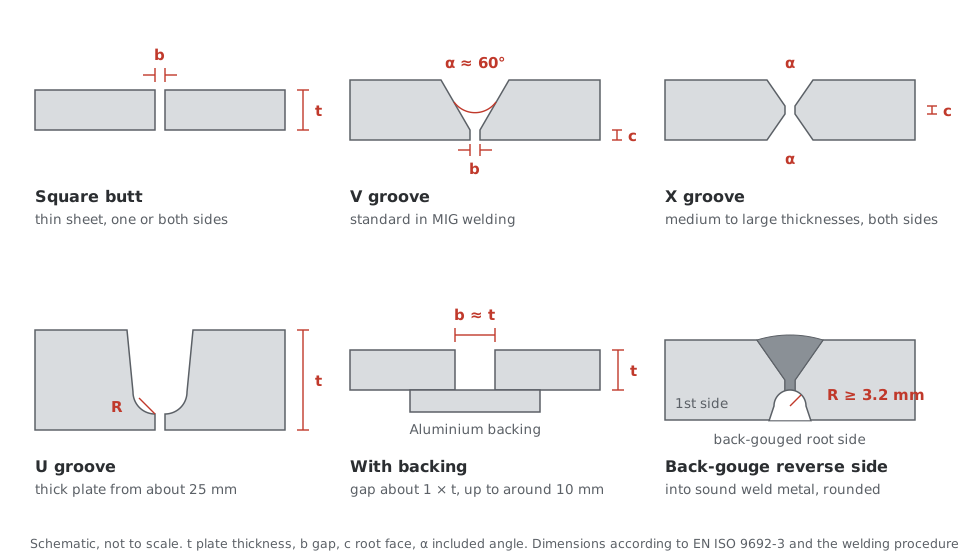
Thin sheets are welded as square butt joints, medium thicknesses with a V groove, thick plates accessible from both sides with an X groove and very thick plates with a U or double-U groove. In MIG welding, a V groove with a 60° included angle is standard.
- In TIG welding the included angle is between 60° and 90°.
- Root passes in the overhead position need at least 110°.
- From a plate thickness of about 25 mm, U and double-U grooves are necessary so that the gas nozzle reaches the root and the root is adequately protected.
Recommendations for gap, root face and angle per plate thickness are given in EN ISO 9692-3, the standard on joint preparation for MIG and TIG welding of aluminium. An extract for MIG welding (131):
| Joint type | Plate thickness t in mm | Angle α or β | Gap b in mm | Root face c in mm |
|---|---|---|---|---|
| Square butt weld with backing, one side | 2 to 4 | – | ≤ 1.5 | – |
| Single-V butt weld, one side | 3 to 5 | 60° to 90° | ≤ 2 | ≤ 2 |
| Single-V butt weld with backing | 3 to 5 | 60° to 90° | ≤ 4 | ≤ 2 |
| Single-Y butt weld, one side | 3 to 15 | ≥ 50° | ≤ 2 | ≤ 2 |
| Single-Y butt weld with backing | 6 to 25 | ≥ 50° | 4 to 10 | 3 |
| Single-bevel butt weld, one side | 4 to 10 | β ≥ 50° | ≤ 3 | ≤ 2 |
| Steep-flanked butt weld with backing | 8 to 20 | β 15° to 20° | 3 to 10 | – |
| Single-U butt weld, one side (root preferably TIG) | 15 to 30 | β 15° to 20° | 1 to 3 | 2 to 4 |
| Square butt weld, both sides simultaneously | 6 to 20 | – | ≤ 6 | – |
| Double-V butt weld (X weld) | over 15 | ≥ 70° | ≤ 3 | ≤ 2 |
| Double-Y butt weld | over 15 | 60° to 70° | ≤ 3 | 2 to 6 |
| Double-U butt weld | from 15 | β 15° to 20° | ≤ 3 | 2 to 4 |
Extract from EN ISO 9692-3:2001, Tables 1 and 2; the text of the standard is binding. Gap b applies to the tacked condition. The values of the qualified welding procedure specification (WPS) are binding.
The standard also gives notes that are important in practice:
- A larger gap allows a smaller included angle. From a gap of 1.5 mm, backing should preferably be used.
- For butt welds made from one side without backing, the edges at the root face should be deburred and chamfered.
- Cleaning liquids based on mineral oil must not be used.
- With helium or argon-helium mixtures, the smaller included angles are sufficient for thick workpieces because of the deeper penetration.
- With extruded profiles, the weld preparation and the backing can already be designed into the profile cross-section. This saves joint preparation and fixing of the parts.
With the heat-treatable 6xxx alloys, the joint also determines the cracking tendency. The weld metal needs enough filler metal: according to ASM at least 50 % with AlSi filler (4043) and at least 70 % with AlMg filler (5356). A square butt joint without a gap is not enough for this; a bevel or gap is necessary. Which filler is suitable is shown in the table under what is different from steel.
How do you get a sound root?
In single-sided welding, the oxide layer stays on the root side. It has to be broken through by the weld pool, so the root needs a reliable penetration zone. In welding from both sides, the reverse side is back-gouged down to sound weld metal.
- Temporary backing: a backing bar with a groove helps to keep the penetration zone even in MIG welding.
- Permanent aluminium backing: the gap must be large enough for the cleaning action of the arc to reach the oxide on the backing, around one plate thickness up to a plate thickness of about 10 mm. The backing lies flush or has a shallow groove and is tacked in place. Projections that protrude into the joint cause lack of fusion.
- Back-gouging the reverse side: by cutting with a milling cutter, router or pneumatic chisel. The bottom of the groove needs a radius of at least 3.2 mm. Sharp chisel notches and saw cuts cannot be reliably fused at their bottom.
Double-sided milling rings on an angle grinder are suitable for back-gouging and for removing fillet welds, see Double-sided milling rings.
Video: bevel, groove and removing a fillet weld with 70 mm milling rings, single and double-sided.
Which brush and which blasting media?
Only stainless steel brushes used exclusively for aluminium. The wire diameter depends on the hardness of the alloy.
| Alloy | Wire diameter of the brush |
|---|---|
| softer alloys | 0.1 to 0.25 mm |
| harder alloys | 0.25 to 0.4 mm |
Wires that are too thin bend at the ends. They then no longer remove the dirt but smear it. Wires that are too thick leave grooves that are too deep. Something similar applies to blasting: the blasting media must be clean and iron-free and should be agreed with the manufacturer.
How do you tack and clamp aluminium correctly?
Tack welds do not belong directly at the start of the weld, and clamping fixtures must position the parts securely without blocking the shrinkage.
The start of the weld is the point of an aluminium weld most susceptible to hot cracking. This is shown in test and simulation by the research project AiF 13.983 B on reducing cracking when welding medium- and high-strength aluminium alloys (University of Magdeburg). The recommendation: place tack welds just after the start of the weld, not directly at it.
Clamping fixtures that are too weak are also a source of defects. In the project AiF 12.239 N, the parts moved relative to each other because of welding distortion. Edge misalignment and gap changed during welding, the weld took up varying amounts of gas, and pores and lack of fusion occurred more frequently. Parts clamped rigidly, on the other hand, crack easily, because aluminium shrinks strongly on cooling. Why a fixture should position rather than confine is shown in the video under what is different from steel.
Frequently asked questions
What included angle for MIG welding of aluminium?
According to EN ISO 9692-3, 60° to 90° for a single-V butt weld made from one side, at least 50° for a single-Y butt weld and at least 70° for a double-V butt weld over 15 mm. For overhead root passes, the ASM handbook gives at least 110°. The values for the individual case are set by the welding procedure specification.
Which standard applies to joint preparation for aluminium?
EN ISO 9692-3 gives recommendations for joint types for MIG and TIG welding of aluminium and aluminium alloys. EN ISO 9692-1 applies to steel.
Does a plasma-cut edge need to be reworked?
For the heat-treatable alloys of the 2xxx, 6xxx and 7xxx series, yes, because cracks can form in the cut edge. For 1xxx, 3xxx and 5xxx this is usually not necessary, as long as the edge is clean.
Why no cooling lubricants during machining?
Residues of oil and cooling lubricant break down in the arc and supply hydrogen, and thus pores. Anyone who machines wet anyway must degrease the joint thoroughly before welding.
Further reading: articles on welding aluminium
The series follows the order of fabrication, from surface preparation to the finished weld. For an overview, see Welding aluminium: what is different from steel.

About the author
Robert Lahnsteiner, Ing., is an International Welding Engineer (IWE) and managing director of MIGAL.CO GmbH. After training in telecommunications and electronics at HTL Braunau, he spent eighteen years in welding technology at Fronius from 1983. Since 2001 he has run MIGAL.CO, the aluminium welding wire manufacturer in Landau an der Isar, together with Martin Erl. His focus is aluminium filler metals, wire manufacturing and wire feeding, and the monitoring of welding processes. Within DVS, the German Welding Society, he has served for around 30 years on technical committee FA03 “Arc welding” and chairs working group 2.4.4 “MIG welding of aluminium”.