







RoboFeed WireManager – feed assist or stand-alone wire feeder with touch display


The RoboFeed WireManager is an electrically driven feed assist for welding wire. A 100 W motor with a quad-roll drive pushes the wire from the drum towards the robot with a constant, adjustable force – so the wire feeder of the welding machine gets its wire almost effortlessly, even through liners of more than 50 m. On its 7-inch touch display it shows wire speed, feed force, package level and consumption, threads the wire automatically, reads the wire label and talks to the PLC over RS-485 – in the i4 version also over Ethernet.
It works in two roles: as a feed assist that pushes the wire with constant force and follows the wire feeder of the welding machine – or as a stand-alone wire feeder that delivers the wire at a constant, set speed for processes without a wire feeder of their own.
- Feed assist or stand-alone wire feeder – force control with constant force, or speed control with constant wire speed; the setpoint comes from the panel, a 0–10 V analog input or Modbus
- Liners of more than 50 m – the drum stays outside the cell, the wire feeder only pulls the last metres
- Package level that survives a power failure – remaining quantity, totaliser and statistics on the display, pre-warning and warning with lamp output
- Automatic threading with retract if the wire gets stuck, teach-in of the liner length, jog keys
- Modbus RTU over RS-485 – actual values, commands and every parameter for the PLC or robot controller
- i4 network version – Ethernet add-on with Modbus TCP, MQTT telemetry and time via NTP, set up on the display
- Firmware 2.0 – new user interface with seven screens, English and German, metric or imperial units, PIN protection
Choose your application
All three views describe the same device – hardware and firmware are identical, only the way you use it differs.
Welding production
Why a feed assist at all?
The friction of the wire in the liner grows exponentially with the sum of the bending angles. Beyond a certain liner length the wire feeder of the welding machine simply cannot pull any more: the wire slips, the arc becomes unstable, the drum has to stand right next to the robot. The RoboFeed WireManager pushes the wire from the drum side with a constant force – the wire feeder only has to pull the last few metres.
Constant feed force
The wire is pressed against the outer wall of the liner instead of being dragged along the inner wall. Set the force so that the wire can be stopped with two fingers at the outlet – the wire feeder then works with the least possible effort.
Feed assist: no connection to the power source needed
RoboFeed stops by itself when the main drive stops and delivers wire when it runs – up to 50 m/min, also with rapidly changing wire speeds. A 24 V interface and Modbus are there if you want them.
Stand-alone wire feeder: constant speed
In speed control the WireManager is the only drive: set speed, ramp and force limit, start from the display, the 24 V input DI3 or Modbus – the wire runs at exactly this speed, independent of any welding machine.
Liners of more than 50 m
The drum stays outside the cell, next to the gate or in the material zone. Drum changes no longer interrupt the robot's working area.
Automatic threading
The WireManager pushes the wire with a set force over a set length. If the wire gets stuck, it retracts and tries again. A teach-in measures the liner length once and stores it.
Jog keys
Forward and back on the screen, slow first and fast after half a second – or via the 24 V inputs DI1 / DI2 of the drive, e.g. from a pendant at the wire feeder.
Less wear
Lower forces in the whole wire feed system mean less wear on liners, drive rolls and contact tips – and a more stable welding process.

Two control modes: feed assist or stand-alone wire feeder
Force control is the classic feed assist: you set the feed force (0–165 N) and the WireManager follows the wire feeder of the welding machine up to a maximum speed. It needs no signal from the power source – when the main drive stops, the WireManager stops.
Speed control is new in firmware 2.0 and turns the WireManager into a stand-alone wire feeder: you set the wire speed, a ramp and a maximum force, and the WireManager delivers the wire at constant speed on its own – no wire feeder of the welding machine needed. Typical uses are processes without their own wire drive: feeding wire into a melt pool or a test rig, cladding and additive processes, or a second wire. Start and stop come from the display, the 24 V input DI3 of the drive or Modbus; the force limit protects the wire if it gets stuck.
Control mode and setpoint are set once in Setup › Drive; the production screen shows the actual values and where the setpoint comes from – panel, 0–10 V analog input or RS-485.
Works with Rolliner NG, Rolliner 3G, Rolliner XL2 and with Softliner or Toughliner conduits. Background: basics of wire transport.


Up and running in four steps
- MountOn the wall with the brackets included or on the optional stand. The panel rotates for vertical or horizontal wire direction.
- ConnectLiner from the drum hood or decoiling aid to the inlet, liner to the wire feeder at the outlet, 115–230 V mains. That's all – no cable to the power source.
- Set upWire type, diameter and drum weight under Setup › Wire package – or simply scan the MIGAL.CO label. Set the feed force, done.
- Thread and weldStart the automatic threading. From now on the WireManager follows the wire feeder of the welding machine on its own.
Would you like to see it in your cell? We will gladly bring a RoboFeed WireManager and show you live how the feed forces in your system drop.
Want to know how much wire is left? See the material & consumption functions.
Material & consumption
Know what is left in the drum – before the robot stops
A 250 kg drum in a closed hood gives no hint of how much wire is left. The WireManager counts every millimetre that passes its drive rolls and shows the remaining quantity in kilograms and percent – large, on the display, with a warning in time for the drum change.

Package level on the display
- Bar and percentage of the remaining wire plus the quantity in kilograms – calculated from wire type, diameter and drum weight
- Pre-warning and warning at two freely set thresholds: the bar turns orange, then red; a banner appears in the header and the lamp output of the drive switches a stack light
- Survives a power failure: the level and the totaliser are kept in battery-backed registers – no SD card, no network needed
- Package change with one tap and a confirmation – or automatically by scanning the label of the new drum
- Wire length since the last package change, feed force, motor current and the speed trend of the last 60 seconds at a glance
Label scanner
The optional barcode scanner reads the MIGAL.CO label (QR or DataMatrix): article number, weight, batch and production date. The package change is only accepted if the article number matches – a wrong wire is rejected.
Totaliser
Wire length, weight, feed runs and wire time since the last reset – battery-backed, resettable on the display or via Modbus.
Statistics
Feed runs, wire, wire time, duty cycle and mean speed for the current shift, the last hour, 24 hours or since start; wire per hour as a bar chart.
Stopwatch
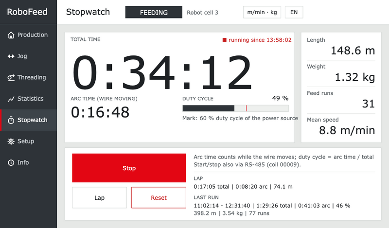
Total time, wire-moving time and duty cycle against the 60 % mark of the power source, plus length, weight and feed runs – for one part, one job or one shift. Lap times included.
Warnings where they are needed
Orange and red on the display, a banner with acknowledge, the lamp output at the drive and the status bits over Modbus – the PLC, the stack light and the operator see the same thing.
Metric or imperial
m/min or IPM, N or lbf, kg or lb, m or ft – one tap in the header switches the whole interface. English and German.

Need the consumption data in your PLC or MES? All counters and the package level are available over Modbus RTU – see automation & integration.
Automation & integration
Everything the display can do, the PLC can do too
Firmware 2.0 adds Modbus RTU over RS-485 – and with the Ethernet add-on of the i4 version Modbus TCP and MQTT: every actual value, every command and every parameter of the WireManager is a register. The 24 V inputs of the drive and the 0–10 V analog input are still there – choose the level of integration that fits your cell.
Interfaces
| Interface | Content | Typical use |
|---|---|---|
| Modbus RTU (RS-485) | Actual values, status bits, start/stop, jog, threading, package change, setpoint, all parameters. Slave ID 1, 19,200 baud 8E1 by default (4,800–115,200 baud, 8N2/8E1/8O1); function codes 01/02/03/04/05/06/15/16 | PLC, robot controller, MES gateway |
| Analog input 0–10 V | Setpoint for feed force or wire speed, scaled between freely set values at 0 V and 10 V; the actual input value is shown on the display | Analog output of the PLC, potentiometer at the wire feeder |
| 24 V inputs DI1 / DI2 | Jog forward / back while the jog screen is open | Pendant at the wire feeder |
| 24 V input DI3 | External start: the rising edge starts the feed, the falling edge stops this start; a stop from the display or the bus has priority, and DI3 applied at power-up does not start the feed. Switching threshold of DI1–DI3 adjustable (5 V or 24 V, default 24 V) | Robot or PLC output |
| Lamp output | Package warning | Stack light at the drum |
| Barcode scanner (optional) | MIGAL.CO label: article number, weight, batch, production date | Drum change with article check |
| Modbus TCP (i4 version) | Same register map and function codes as Modbus RTU over Ethernet: port 502, up to four clients at the same time, any unit ID | PLC over Ethernet, SCADA, Node-RED |
| MQTT (i4 version) | Actual values as JSON at a set interval (speed, force, motor current, load, state, package level, remaining quantity, wire since package change, batch, timestamp) and events for package change, package warnings and drive fault; broker, topic, login and interval set on the display | IoT platforms, MES, dashboards |
| NTP and IP (i4 version) | Clock set from a time server after every start and hourly; DHCP or static IP address | Correct timestamps in MQTT messages and on the display |
Modbus register map (excerpt)
Addresses are 1-based, 32-bit values high word first, all values metric regardless of the display unit.
| Address | Content | Unit / range |
|---|---|---|
| Coils 00001–00004 | Feed on/off · jog forward · jog back · threading on/off | Jog is a dead-man command: repeat within 500 ms or the drive stops |
| Coils 00006–00008 | Package change · totaliser reset · acknowledge drive fault | pulse |
| Input 30001 | Status: feeding, jog, threading, wire moving, pre-warning, warning, drive fault, CAN link, setup locked, control mode, setpoint source | bits 0–13; discrete input 10015 is a 1 s heartbeat |
| Inputs 30002–30006 | Wire speed · wire speed with direction · feed force · motor current · load factor | 0.01 m/min · 0.1 N · mA · % |
| Inputs 30010–30018 | Package level · remaining quantity · wire since package change · totaliser length and weight | % · g · mm · 0.1 m · g |
| Inputs 30019–30037 | Feed runs, wire time, operating time, firmware version, drive state, threading progress, motor status, stopwatch | |
| Holding 40001–40002 | Command (start, stop, jog, threading, package change, resets, stopwatch, restart) · RS-485 setpoint | 0–165 N or 0–50.0 m/min |
| Holding 40011–40017 | Control mode · setpoint source · feed force · max. speed · wire speed · max. force · ramp | stored in the device |
| Holding 40018–40046 | Analog scaling, wire direction, DI3 start, input threshold DI1–DI3, jog and threading parameters, CAN node, wire type, diameter, density, drum weight, warning thresholds | out-of-range values are rejected |
The complete register map is part of the manual. Values outside the permitted range return a Modbus exception; parameters are stored in the device, the bus setpoint is not.
Setpoint from the PLC
Set the setpoint source to RS-485 and write the force or speed to one register. Start, stop and threading work regardless of the setpoint source.
Safe by design
Jog over the bus is a dead-man command and only possible from standstill. A heartbeat input lets the PLC detect a dead link, out-of-range values are rejected.
Status in one word
Feeding, jog, threading, wire moving, package warnings, drive fault and the setup lock – fourteen bits in one input register, also available as discrete inputs.
Two control modes, one map
Force control with speed limit or speed control with force limit and ramp – switched by one holding register; the drive parameters are kept in the device.
Teach-in and totaliser remote
Package change, totaliser reset, fault acknowledge and the stopwatch can be triggered from the controller – every reset is also possible on the display.
PIN protection
The setup can be locked with a PIN on the display; the lock state is visible to the PLC as a status bit.
Everything the PLC writes, the operator sees
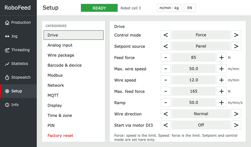
Parameters written over Modbus appear immediately on the display – and the other way round. The setup page Modbus shows slave ID, baud rate, parity and the frame and CRC counters, so a wiring or baud-rate problem is found in seconds.
RoboFeed WireManager i4 – the network version. With the Ethernet add-on the same device joins your network with a DHCP or static address: Modbus TCP with the same register map as RS-485, MQTT telemetry with JSON values and events, and the clock set via NTP. Everything is set up on the display under Setup › Network, MQTT and Modbus – no PC software needed. A Node-RED example flow with dashboard is available on request.
Interested in the i4 version or in a register map for your controller? Write to info@migal.co or use the contact form.
Seven screens, one touch display
Everything the WireManager measures and does is available directly at the drum – without a PC, browser or network. The side navigation is always visible, the header shows the device state, the device name, the units and the language. Below you see all seven screens of firmware 2.0 (English version; the user interface is available in English and German).
1 · Production – the live view for the operator
The wire speed is shown in large digits in m/min or IPM. Next to it: the actual feed force, the wire length since the last package change and the motor current. The START/STOP key switches the feed; below it you see where the setpoint comes from – panel, 0–10 V or RS-485. The graph shows the wire speed of the last 60 seconds, including every stop of the main drive. The package column shows the remaining wire as a bar with the pre-warning and warning marks, in percent and kilograms, together with wire type and diameter; Change package resets the level after a confirmation. The state badge in the header shows READY, FEEDING, JOG, THREADING, FAULT or NO MOTOR.
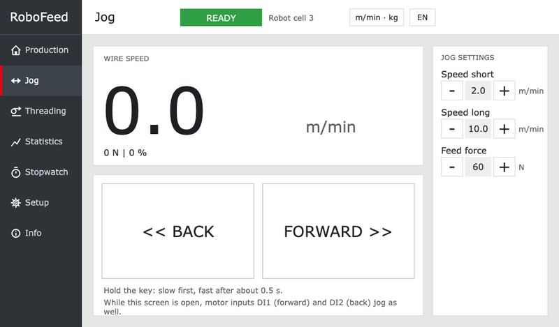
2 · Jog – move the wire by hand
Two large keys move the wire back or forward as long as they are held – slowly first, after about half a second at the long-jog speed. The speed and force for jogging are set on the right. While this screen is open, the 24 V inputs DI1 and DI2 of the drive jog as well, e.g. from a pendant at the wire feeder. Jogging is only possible from standstill and is a dead-man function: release the key and the wire stops.
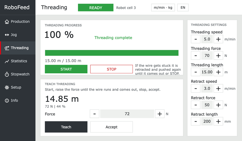
3 · Threading – feed the wire through the liner automatically
The automatic threading pushes the wire with the threading force over the threading length; the progress bar shows how far the wire has travelled. If the wire gets stuck, the drive retracts it by the set length and pushes again until it comes out or you press STOP. Teach threading finds the right values once: start, raise the force until the wire runs and comes out at the wire feeder, stop – the measured length and force are taken over as threading values with Accept.
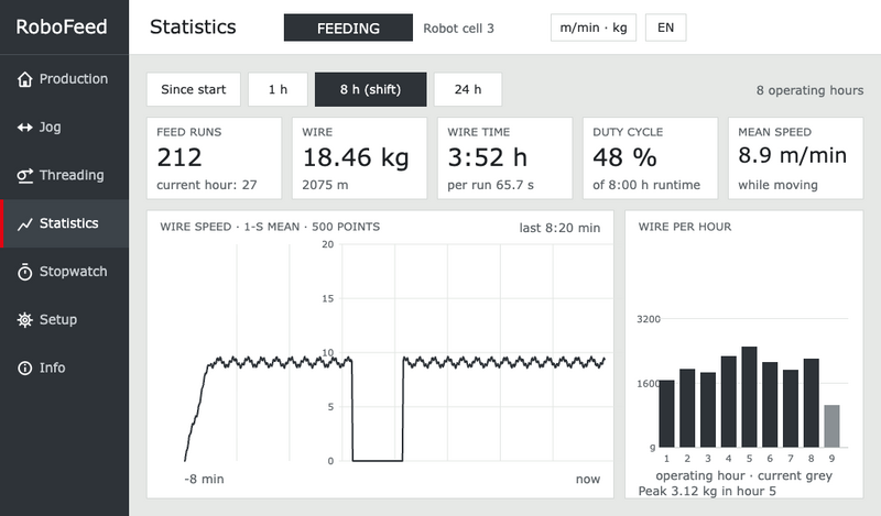
4 · Statistics – the shift at a glance
Four periods – since start, 1 h, 8 h (shift) and 24 h – and five key figures: feed runs, wire in kilograms and metres, wire time, duty cycle of the runtime and the mean speed while the wire was moving. The graph shows the wire speed as 1-second mean over the last eight minutes, the bar chart the wire consumption per operating hour. The values are kept in the device and do not need a network.
5 · Stopwatch – measure one part, one job or one shift
The stopwatch counts the total time and, separately, the arc time – the time in which wire actually moved. The ratio is the duty cycle, shown against the 60 % mark of a typical power source. On the right: wire length, weight, feed runs and mean speed of the current run. Lap stores an intermediate result, Reset clears the run; the last run stays visible. Start and stop also work over RS-485.
6 · Setup – eleven categories, one list
All settings are grouped in eleven categories: Drive (control mode, setpoint source, feed force, speed limits, ramp, wire direction, start via motor DI3), Analog input (scaling of the 0–10 V input), Wire package (wire type, diameter, density, drum weight, warning thresholds), Barcode & device (including the switching threshold of the motor inputs DI1–DI3), Modbus (RTU: slave ID, baud rate, parity, counters; Modbus TCP on/off), Network (on/off, DHCP or static address, status, MAC address), MQTT (broker, port, topic, login, interval, status), Display (brightness, dimming, language, units), Time & zone (with NTP server), PIN and Factory reset. Values are changed with the −/+ keys or typed on the on-screen keyboard; every parameter has its limits and is stored in the device. With a PIN set, the setup, jog and threading settings are locked for the operator.
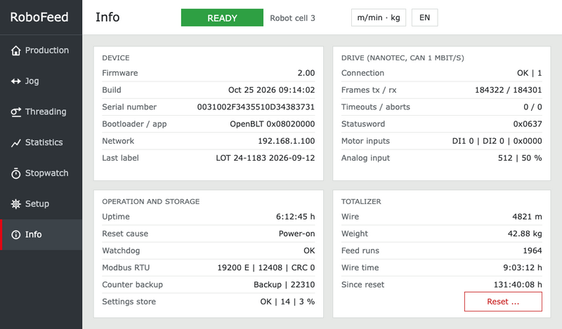
7 · Info – diagnostics without a laptop
Firmware version, build, serial number, network address and the last wire label read; the state of the CAN link to the drive with frame counters, motor status word, the 24 V inputs and the analog input; uptime, reset cause, watchdog, Modbus traffic and the state of the counter backup and the settings store. The totaliser shows wire, weight, feed runs and wire time since the last reset and can be reset here.
Technical data
| Wire feed speed | 0–50 m/min |
| Feed force | 0–165 N, continuously adjustable |
| Operating modes | Feed assist: force control with constant force (speed limit) · stand-alone wire feeder: speed control with constant wire speed (force limit, ramp) |
| Setpoint sources | Panel, analog input 0–10 V, Modbus RTU or TCP |
| Drive | 100 W motor, quad-roll drive, 24 V inputs DI1–DI3 for jog and start, lamp output |
| Wire diameter | 0.8–1.6 mm (larger diameters on request) |
| Wire types | Steel, aluminium, stainless steel, silicon bronze, metal-cored and flux-cored wire |
| Liner length | More than 50 m between wire package and robot (Rolliner NG, 3G, XL2, Softliner, Toughliner) |
| Display | 7-inch touch display, 1024 × 600 px, English/German, metric or imperial units, PIN protection |
| Interfaces | RS-485 Modbus RTU (slave ID 1–247, 4,800–115,200 baud), analog input 0–10 V, 24 V inputs, lamp output, barcode scanner (optional) |
| Network (i4 version) | Ethernet add-on: Modbus TCP (port 502), MQTT (JSON, without TLS), NTP; DHCP or static IP address |
| Memory | Package level, totaliser and statistics battery-backed (CR1220); settings in internal flash |
| Power supply | 115–230 V / 50–60 Hz |
| Dimensions L × W × H | 440 × 255 × 170 mm |
| Weight | 9.9 kg |
| Mounting | Wall brackets included, optional stand; panel rotatable for vertical or horizontal wire direction |
Scope of delivery
- RoboFeed WireManager with wall-mount brackets and mains cable
- Feed rolls and inlet/outlet guides for the ordered wire type, wire diameter and liner
- Firmware 2.0 with English and German user interface
Optional
- Stand for floor mounting
- Barcode scanner for the MIGAL.CO label (QR and DataMatrix code)
- Additional feed roll sets for ferrous and non-ferrous wires, inlet/outlet guides 1/2" and 1/4"
- Rolliner, Softliner and Toughliner conduits, drum hoods and decoiling aids
- Ethernet add-on for the i4 network version (Modbus TCP, MQTT, NTP)
Accessories


