


Wiresensor MWS-3 – wire feed monitoring with touch display
COMING SOON
The Wiresensor MWS-3 is currently in development. The images show a design study; technical data is preliminary and may change. Would you like to be informed about the market launch or test a pre-series unit? Write to info@migal.co.
See your wire feed at the machine – not only in the network.
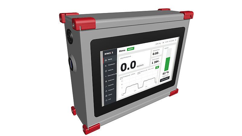
The idea: one device for the operator, the maintenance team and the PLC
The Wiresensor MWS-2 measures the true wire movement with a slip-free two-roller encoder and compares every part against a taught good part. It is a pure edge device: you look at it through a browser.
The MWS-3 brings this measurement to the welding cell itself. A bright 7-inch touch display shows wire feed speed, motor current, wire length and the remaining quantity in the drum – live, large and readable from a distance. The operator sees at a glance whether the wire is running, how much is left and whether an alarm is pending. No network, no PC, no browser required.
Three products in one housing
-
Wire feed meter and consumption counter – every weld is recorded with duration, average feed speed, average motor current and wire consumption. Totals, history and remaining package quantity are always visible on the display.
-
Process monitor – the complete golden-part monitoring of the MWS-2: teach-in, envelope comparison weld by weld, trend warning for creeping roll wear, programs, stopwatch and simulator.
-
Machine interface – six configurable alarms, four programmable 24 V outputs, six 24 V inputs and Modbus RTU over RS-485 for the PLC.
Why measure at all?
Welding power sources do not measure the wire speed – they derive it from the rotation of the feed motor. Slip between drive rolls and wire, a worn liner or a wire end in the drum therefore stay invisible to the machine. The MWS-3 measures directly on the wire, independent of the power source and the robot controller. It can be retrofitted to any welding system, regardless of the manufacturer.
Thanks to the digital encoder there is no annual calibration: the measuring wheel counts pulses, it does not drift.
What the operator sees
The home screen is designed for the shop floor: large numbers, clear colours, no menus to click through. Shown in the preview below (design study, German user interface):
-
Wire feed speed in m/min or in/min, updated ten times per second.
-
Motor current of the wire feeder – the second indicator for friction, worn rolls or a blocked liner.
-
Wire length of the current part and the utilisation of the cell.
-
Package level as a bar with the remaining quantity in kilograms – one tap opens the package setup.
-
Status and alarms – six alarm fields, green or yellow, plus a status line with the active program.
Start, stop, teach-in, stopwatch and settings are one tap away. The interface is available in English and German; further languages are prepared. Metric and imperial units can be switched for the whole device.
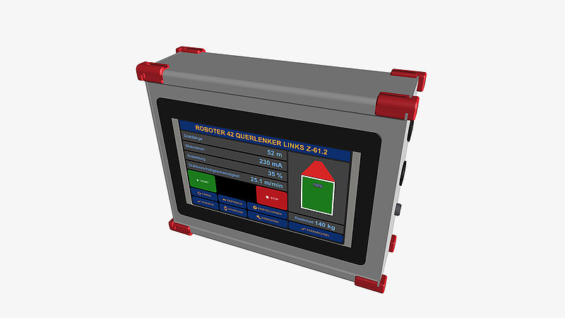
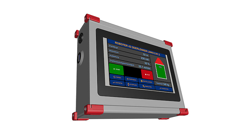
Consumption, totals and history
Every time the wire runs for longer than 0.2 s, the MWS-3 records a weld: start time, duration, average feed speed, average motor current, wire length and wire weight. The last weld is always shown on the home screen.
-
Totaliser – number of welds and total consumption in kilograms and metres since the last reset. Stored battery-backed, survives a power failure.
-
History – every weld is logged on the microSD card. Browse and filter by date directly on the display, or take the card to the office: the data is stored as CSV, ready for Excel.
-
Package level – enter wire type, diameter and net weight of the spool or drum. The MWS-3 calculates the remaining quantity from the measured wire length and warns before the package runs empty – on the display, on a 24 V output and, if connected, via Modbus or MQTT. Partly used packages can be entered as well.
Motor current: the second eye on the drive
An external clamp-on current sensor on the feed motor (0–5 V or 4–20 mA) gives the MWS-3 a second measurement: the effort the drive needs to push the wire. Rising motor current at constant wire speed means rising friction – a liner that is wearing out, a contact tip that is sticking, a drum that is nearly empty. The high motor current alarm reports this long before the wire actually stops.
Six alarms, four outputs
Each alarm has its own threshold and can be switched off individually. Alarms are evaluated at the end of every weld and shown as green or yellow fields on the home screen:
-
Motor current high
-
Package empty
-
Wire feed speed low / high
-
Consumption per weld low / high
The four 24 V high-side outputs (0.5 A, short-circuit proof, with diagnostics) can be assigned freely: always on/off, heartbeat, wire moving, high or low feed speed, high motor current, high or low consumption, package low, alarm in fail-safe logic, monitoring active, NOK pulse, trend warning or device OK. The six 24 V inputs accept a part start signal, a program number from the PLC, an alarm acknowledgement and a counter reset.
Golden-part monitoring on board
Everything that made the MWS-2 a reference-based process monitor is included – operated on the touch display instead of in a browser:
-
Teach-in – record a few verified good parts, the MWS-3 builds a mean curve with a statistical tolerance band for every single weld. A quality indicator tells you when the reference is good enough.
-
Monitoring – the live signal is compared against the envelope weld by weld. Green inside the band, red outside. Deviations are reported with part, weld, time and maximum deviation; the alarm output stops the line or switches a signal lamp.
-
Trend warning – worn rolls first show up as rising scatter of the wire speed. The MWS-3 warns while the parts are still good: plan the maintenance instead of stopping the line.
-
Programs – up to 16 references with their own thresholds, selected on the display, via the digital inputs or over Modbus.
-
Stopwatch – total time, arc time, wire length, wire weight and duty cycle of one part, for welding procedure specifications and cost calculation.
-
Simulator – demonstrate and train the complete workflow without a welding cell.
Modbus RTU for the PLC
The RS-485 interface speaks Modbus RTU (device ID 1–247, 4800 to 115200 baud). The register map provides live speed, motor current, last weld, totals, package level, alarms and the state of the device. A compatibility profile mirrors the register layout of common wire feed monitors on the market, so existing PLC programs can be reused; a native metric profile adds the MWS-specific values. The same protocol is available over the USB service port.
Network – when you want it
The MWS-3 works completely standalone. For plants that want the data in their MES, SCADA or database, an Ethernet/PoE option adds the web dashboard, MQTT messages and NTP time synchronisation known from the MWS-2 – and makes the device a data source for RoboCenter.
Built for the shop floor
-
Robust housing – aluminium enclosure with protective corner bumpers, glove-friendly capacitive touch, bright IPS display readable in daylight.
-
24 V DC supply from the cell – no extra power supply.
-
Battery-backed real-time clock and non-volatile counters: totals and package level survive a power failure.
-
Firmware update from a microSD card or over USB in a few minutes; the new firmware is verified before it is activated.
-
PIN protection for setup and teach-in, so that nobody changes thresholds by accident.
What you gain
| Transparency at the cell | Wire speed, consumption, motor current and remaining quantity visible to everyone – no login, no network. |
| No surprises at the drum | Remaining wire quantity at a glance, warning output before the package runs empty. |
| 100 % monitoring | Every weld of every part compared against the taught good part – retrofittable regardless of the equipment manufacturer. |
| Predictive maintenance | Trend warning and motor current reveal creeping wear of rolls, liners and contact tips early. |
| Complete documentation | Every weld with duration, speed, current and consumption, archived on microSD as CSV. |
| PLC integration without engineering | 24 V inputs and outputs plus Modbus RTU – connected in an hour, not in a project. |
| No calibration service | Digital encoder instead of an analogue sensor: no annual recalibration, no drift. |
MWS-2 or MWS-3?
| Wiresensor MWS-2 | Wiresensor MWS-3 | |
|---|---|---|
| Operation | Web browser | 7-inch touch display at the cell, web browser optional |
| Network | Ethernet/PoE required for operation | Standalone; Ethernet/PoE as option |
| Wire speed, wire length | yes | yes |
| Motor current | – | yes, external clamp-on sensor |
| Weld history, totals, package level | event archive, package level | per-weld history, totaliser, package level, all on the display |
| Golden-part monitoring, trend warning | yes | yes |
| Digital inputs / outputs | 1 / 4 | 6 / 4 |
| PLC interface | MQTT | Modbus RTU (RS-485), MQTT with network option |
| Typical use | Networked cells, data acquisition, labs | Cells without network, operator information, consumption tracking |
Good to know
The MWS-3 detects deviations from the taught good condition – it complements the qualification of your welding process, it does not replace it. After changing welding parameters or the robot program, simply teach the reference again: a few parts, one button.
Technical data (preliminary)
| Display | 7-inch IPS touch display, 1024 × 600 pixels, 850 cd/m², capacitive touch |
| Wire diameter range | 0.8 mm – 1.6 mm (larger on request) |
| Measuring principle | Two-roller measuring wheel with incremental encoder, 600 pulses per revolution |
| Resolution | 0.0286 mm (quadrature evaluation) |
| Accuracy | 0.7 % at 10 m/min and 0.1 s sampling |
| Wire feed speed | 0 – 50 m/min (0 – 1970 in/min) |
| Motor current input | External clamp-on sensor, 0 – 5 V or 4 – 20 mA, 16-bit, zero and span adjustable; second analogue input for a second sensor |
| Digital inputs | 6 × 24 V (part start, program number, acknowledge, counter reset) |
| Digital outputs | 4 × 24 V high-side, 0.5 A, short-circuit proof, with diagnostics, freely assignable |
| Alarms | Motor current high, package empty, wire feed speed low/high, consumption low/high – thresholds adjustable, individually switchable |
| PLC interface | Modbus RTU over RS-485, ID 1–247, 4800 – 115200 baud |
| Service interface | USB (Modbus, console, firmware update) |
| Network (option) | Ethernet 10/100 Mbit/s, Power over Ethernet, web dashboard, MQTT 3.1.1 and 5, NTP |
| Data logging | microSD card: welds, events and statistics per part, CSV export |
| Monitoring | Teach-in with up to 16 programs, envelope comparison per weld, trend warning, stopwatch, simulator |
| Real-time clock | Battery-backed, time zone and daylight saving configurable |
| Units | Metric or imperial (m/min ↔ in/min, m ↔ ft, kg ↔ lb, mm ↔ in), switchable on the device |
| Languages | English, German (further languages prepared) |
| Power supply | 24 V DC (18 – 30 V), typically 10 W |
| Protection | Front IP54, rear IP20 (target) |
| Operating temperature | 0 – 50 °C |
| Enclosure | Aluminium, approx. 230 × 170 × 60 mm (design study, final dimensions to follow) |
Scope of delivery
-
MWS-3 display unit with connectors for 24 V DC, wire sensor, RS-485, USB and digital inputs/outputs.
-
Wire sensor (encoder) with 1.5 m cable and plug.
-
Optional: clamp-on motor current sensor, Ethernet/PoE option, mounting kit for panel or bracket installation.