






Which joint types can be arc brazed?
Essentially fillet seams, flange seams and square butt seams on sheet up to 3 mm. In production, the fillet seam on a lap joint predominates; in repair, the square butt seam on a butt joint.
Unlike furnace or flame brazing, arc brazing draws hardly any filler metal into a narrow gap. The capillary action is low, and the filler metal lies on the joint as a bead, as with a weld. Joint preparation is therefore usually not needed.
Joint types and favourable gap widths
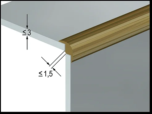
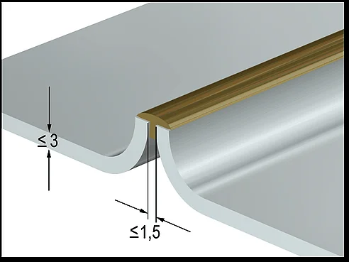
For almost all joint types: gap below 1.5 times the thinner sheet thickness tmin, 2 mm at most. For corner joints and edge seams, the limit is 1.5 mm.
| Joint and seam | favourable gap | maximum |
|---|---|---|
| Fillet seam on a lap joint | below 1.5 × tmin | 2 mm |
| Fillet seam on a joggled lap joint | below 1.5 × tmin | 2 mm |
| Fillet seam on a lap joint, three sheets | each gap below 1.5 × tmin | both gaps together 3 mm, sheets usually around 1 mm |
| Flange seam | below 1.5 × tmin | 2 mm |
| Square butt seam on a butt joint | below 1.5 × tmin | 2 mm |
| Fillet seam on a T-joint | below 1.5 × tmin | 2 mm |
| Fillet seam on a corner joint | below 1.5 × tmin | 1.5 mm |
| Edge seam | below 1.5 × tmin | 1.5 mm |
Gap widths to DVS 0938-1:2012, Table 6, for usual sheet thicknesses up to 3 mm. tmin is the thickness of the thinner sheet.
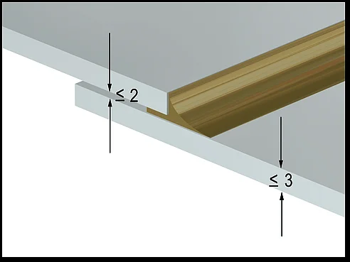
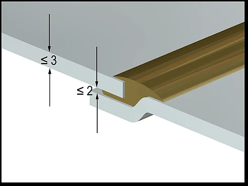
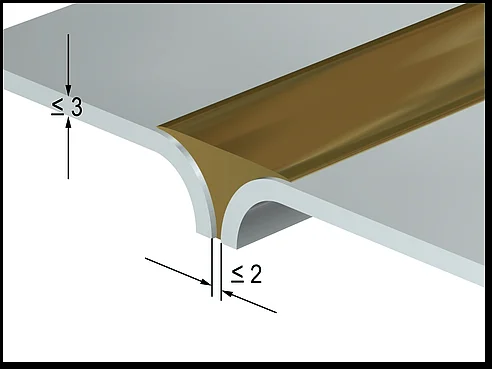
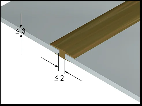
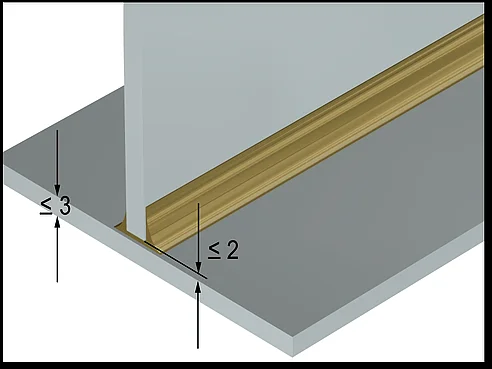
Fillet seam on a lap joint: the standard seam
The sheets lie on top of each other, and the filler metal fills the fillet between the edge of the upper sheet and the lower sheet. The seam is easy to prepare, tolerates variations and is the seam most often brazed in car body construction.
- Torch: Aim the arc at the edge of the upper sheet and the lower sheet. If the upper sheet melts, the heat is too high or the torch angle is too large. Settings: MIG brazing.
- Joggled lap joint: One sheet is joggled by about the sheet thickness. This keeps the surfaces roughly flush, for example on visible outer surfaces.
- Three sheets: possible if the sheets are around 1 mm thick and both gaps together do not exceed 3 mm.
Flange seam: joining thin sheets at the edge
In a flange seam, the sheet edges are bent up, and the filler metal joins the flanges at their top edge. It is typical on thin car body sheet, for example in laser brazing of roof seams.
Because the flange is formed, it is under stress. That is exactly where SLV München found the damage, in the bending tension zone of the flange joint (Aicher and Cramer, DVS-Berichte 244, 2007). DVS 0938-1 generally advises against brazing on deformed contours under tensile stress because of the risk of filler metal penetration. For flange seams this means: avoid tight bending radii and heavily pre-stretched sheet. More in Seam defects and braze cracking.
How important is the gap?
A small gap helps strength; a large one harms the seam. The filler metal flows into the gap and enlarges the bonded area, but as the gap widens, the number of pores rises.
In investigations in Chemnitz, a gap tended to increase joint strength because the bonding area between filler metal and lower sheet grew. Gaps above 0.5 mm, on the other hand, made the number of pores rise markedly (Kusch and Podlesak, DVS-Berichte 275, 2011).
Larger gaps can be filled with a weaving torch or a backing support. It is better to avoid them by design.
Design rules for brazed components
In principle, the same rules apply as for gas-shielded welded structures. DVS 0938-2 names a few special points that result from the dissimilar filler metal.
- Edge distance: more than 2 mm, especially for sheet up to 1 mm.
- Hole brazing: From a hole diameter of 6 mm, it achieves the strength of a corresponding resistance spot weld on unalloyed deep-drawing sheet up to 1 mm. Slotted holes are also recommended.
- Connecting smaller cross-sections: The total seam length must be greater than the cross-section loaded in tension.
- Allow shrinkage: If the component cannot shrink freely during cooling, there is a risk of hot cracks, especially with seams over 50 mm.
- Adhesive seams: at least about 25 mm distance; otherwise the adhesive burns, giving off toxic fumes, and disturbs the seam.
- Seam transition: For dynamically loaded components, the wetting angle between filler metal and sheet should be below 90°.
The drawing symbol for a brazed seam is shown on the page Processes at a glance.
Frequently asked questions
What is a flange seam?
A seam on two bent-up sheet edges that are joined at their top edge. It is suited to thin sheet and is often used in brazing on car body parts.
What gap for a lap joint?
Below 1.5 times the thinner sheet thickness, 2 mm at most. A small gap of up to about 0.5 mm is ideal.
Does MIG brazing need joint preparation?
Usually not. The sheets must be clean; bevels or opening angles as in welding are not needed.
Can a butt joint be brazed?
Yes, as a square butt seam. It is the most common seam shape in repair. The gap should be below 1.5 times the sheet thickness and no more than 2 mm.
How far must the brazed seam be from an adhesive seam?
At least about 25 mm.
Further reading: articles on arc brazing
The series in the order in which the questions arise in practice: from the process via filler metal, gas and base material to the finished seam. For an overview, see Arc brazing.

About the author
Robert Lahnsteiner, Ing., is an International Welding Engineer (IWE) and managing director of MIGAL.CO GmbH. After training in telecommunications and electronics at HTL Braunau, he spent eighteen years in welding technology at Fronius from 1983. Since 2001 he has run MIGAL.CO, the aluminium welding wire manufacturer in Landau an der Isar, together with Martin Erl. His focus is aluminium filler metals, wire manufacturing and wire feeding, and the monitoring of welding processes. Within DVS, the German Welding Society, he has served for around 30 years on technical committee FA03 “Arc welding” and chairs working group 2.4.4 “MIG welding of aluminium”.